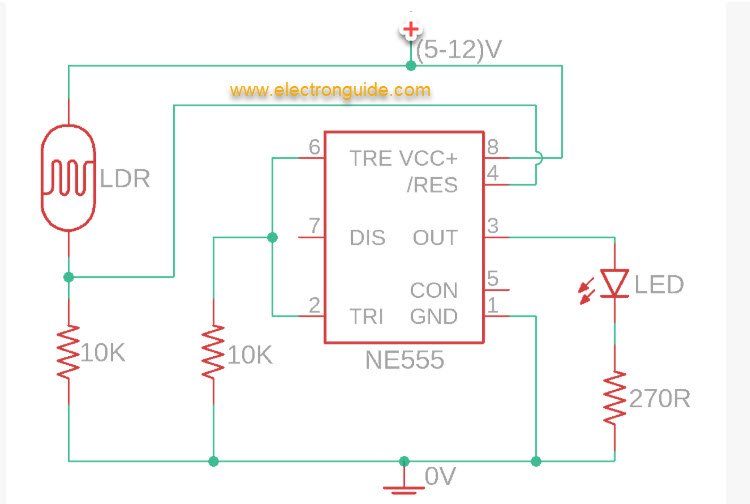
This tutorial outlines the design and implementation of both a light sensor circuit and a darkness detection circuit using a 555 timer IC in conjunction with a minimal set of electronic components.
In its light sensor configuration, the circuit activates the output when the intensity of light incident on the Light Dependent Resistor (LDR) exceeds a predefined threshold. This threshold can be precisely adjusted using a potentiometer, enabling control over the circuit’s sensitivity.
In contrast, when configured as a darkness detector, the circuit triggers the output when the ambient light level falls below a specified threshold. In this mode, the circuit operates inversely to the light sensor configuration. Such a setup is commonly employed in applications like automatic street lighting systems, where operation is dependent on environmental light conditions.
Components Required:
Power supply (5V–12V)
Breadboard jumper wires
2 × 10 kΩ resistors
LDR (Light Dependent Resistor / Photoresistor)
Breadboard
270 Ω resistor (for LED)
Output device (e.g., LED, buzzer, etc.)
555 Timer IC
Questions & Answers (0)
No questions yet — be the first to ask!
Ask a Question